 |
 |
 |
 |
|
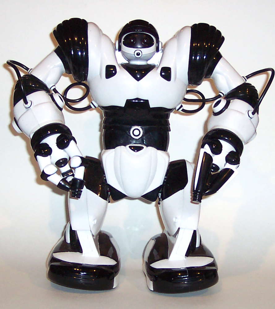
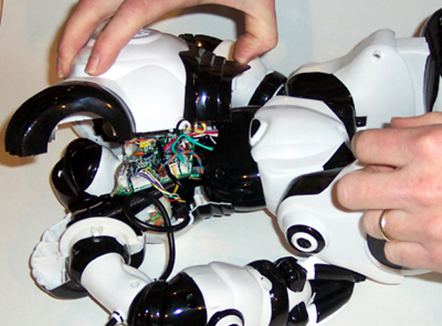
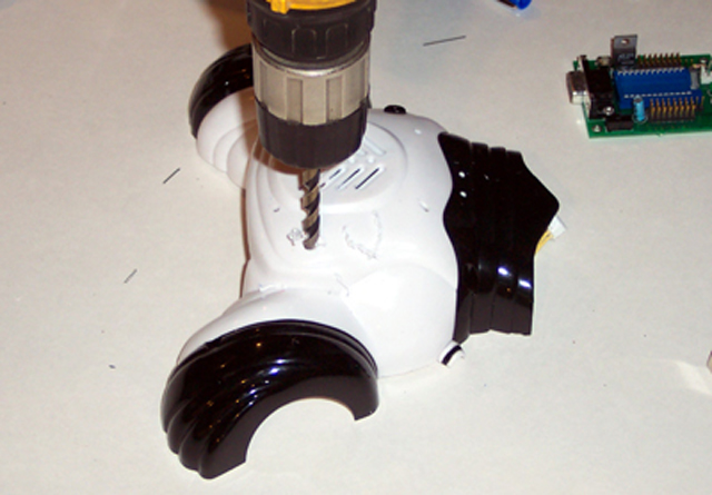
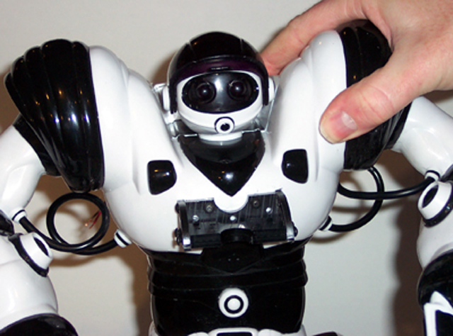
Front view of the next Robosapien getting ready for assimilation
|
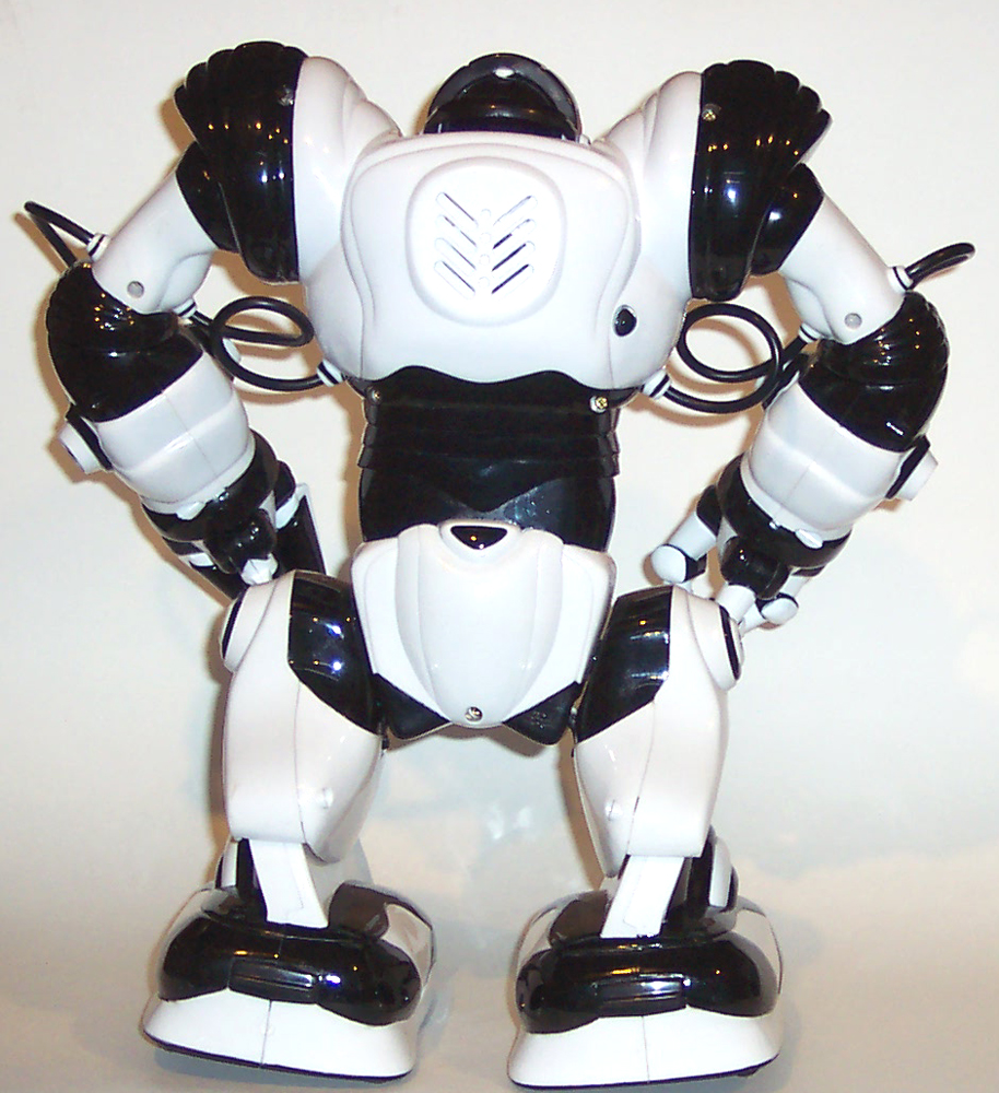
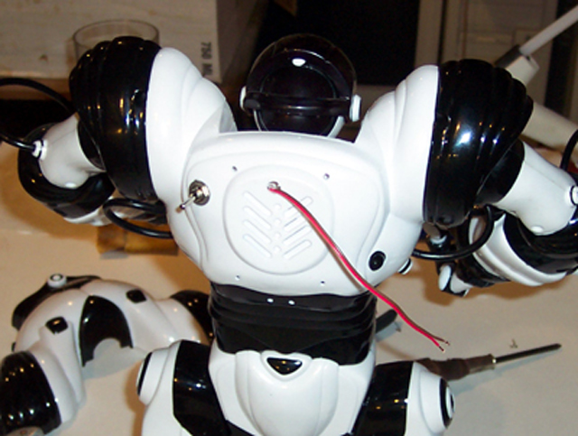
Back view..We can make him better..stronger...faster..
|
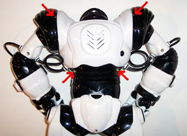
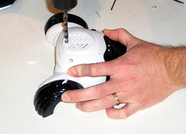
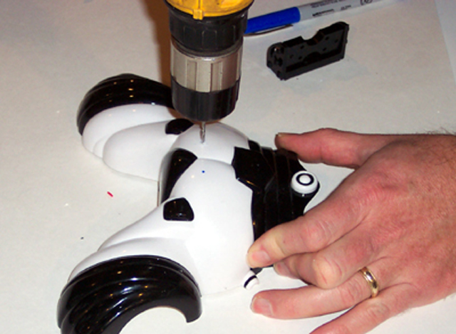
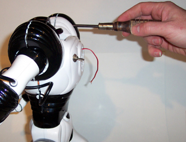
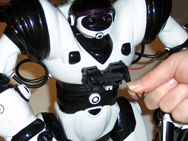
Locate the 4 screws as shown with the arrows.
|
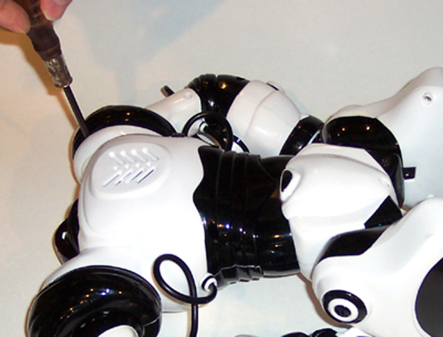
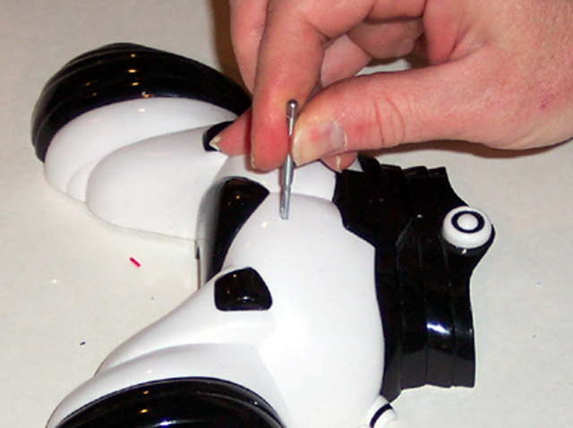
Loosen the 4 screws to remove the back plate.
|
 |
 |
 |
 |
|
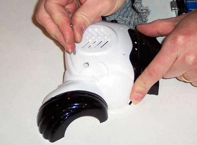
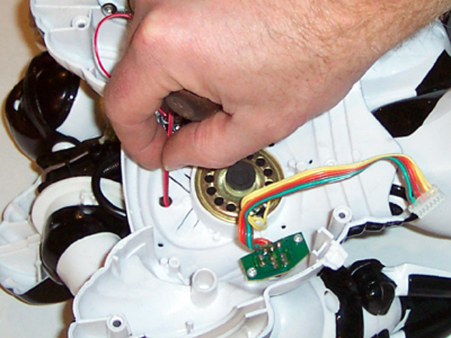
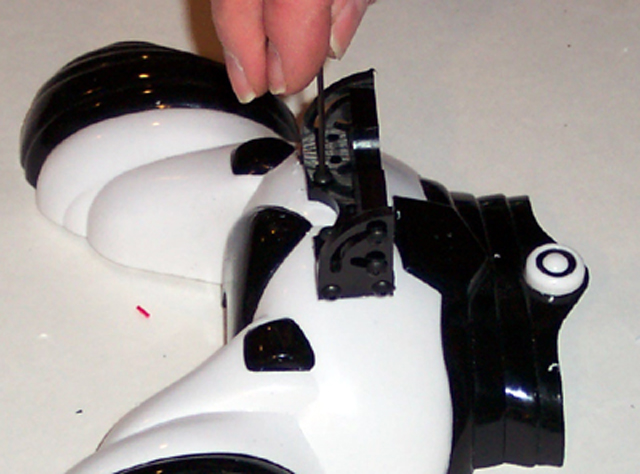
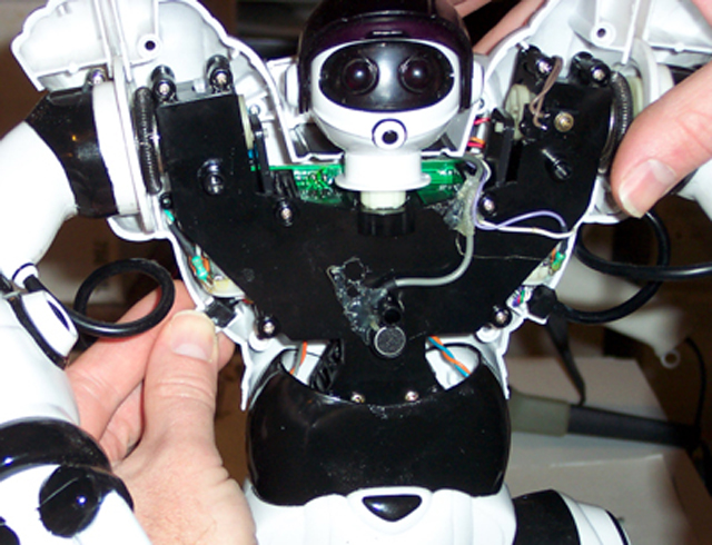
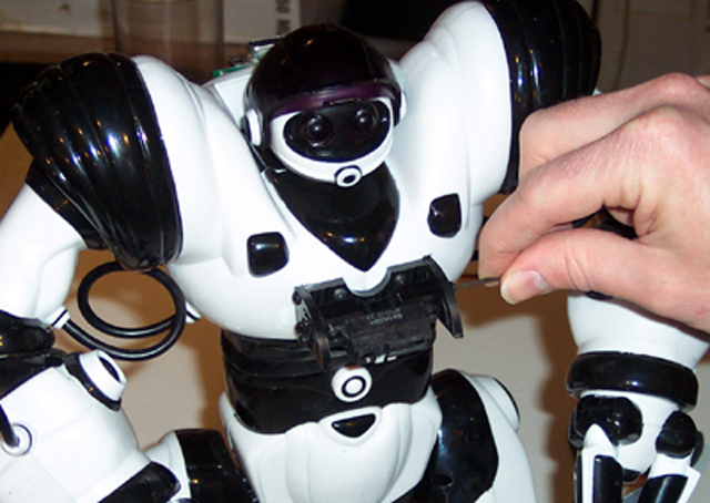
Carefully seperate the back from the body.
|
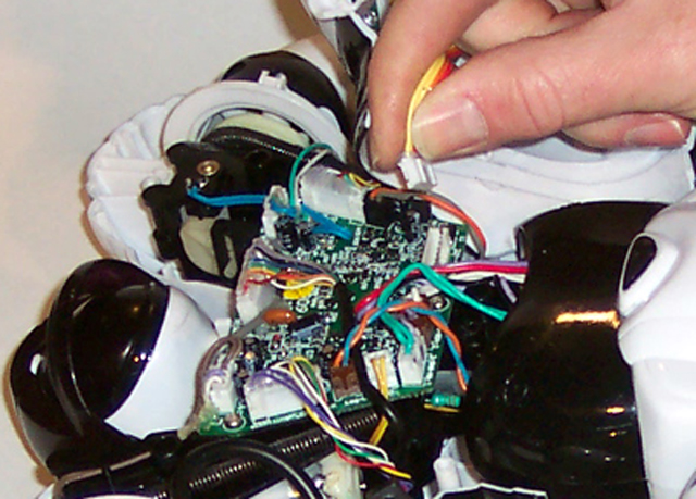
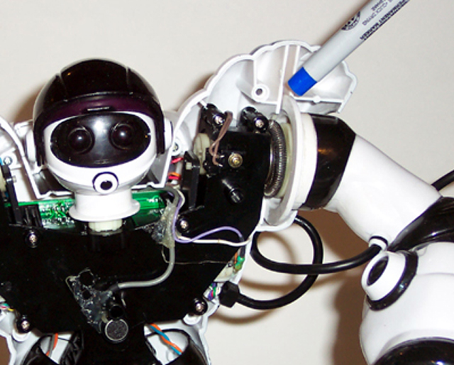
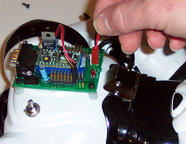
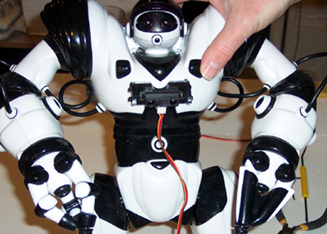
Unplug the cable connecting the back electronics to the circuit board.
|
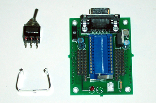
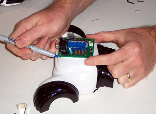
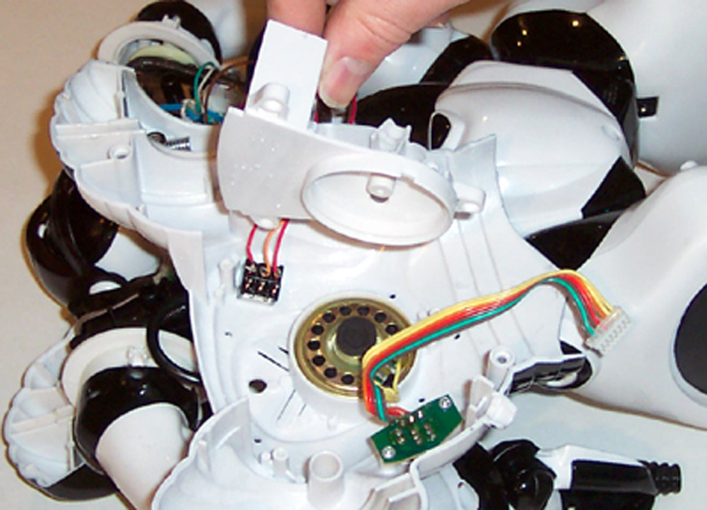
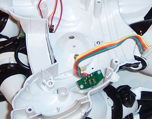
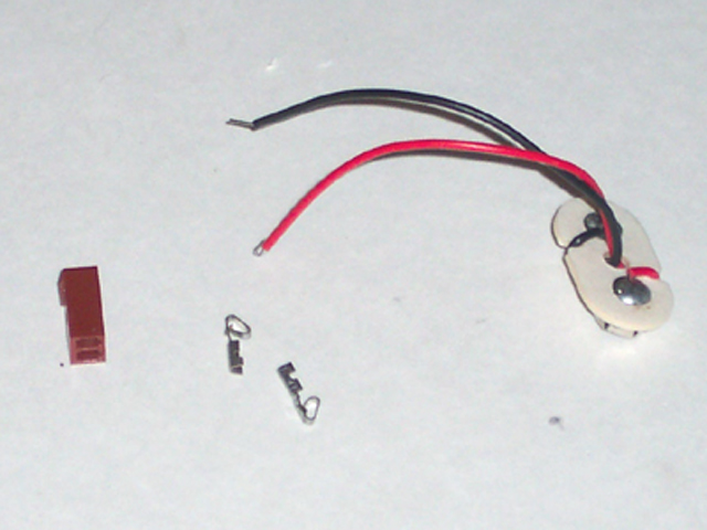
Locate these parts. We will need to mark the locations for drilling.
|
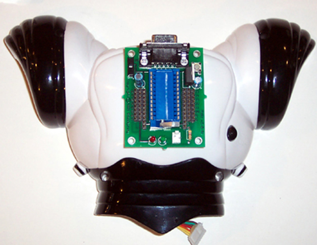
Align the motherboard on the robosapiens back plate.
|
 |
 |
 |
 |
|
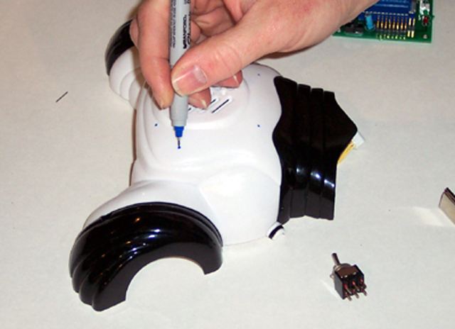
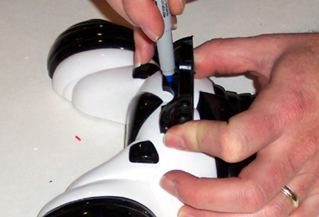
Carefully mark the location of the holes on the Robosapien back. This step is very important.
The back plate is not flat, so check and check again that the holes all line up.
|
Mark the battery clip hole locations.
|
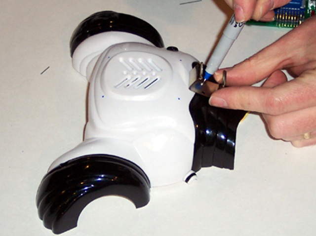
Mark the switch hole location.
|
Using a #43 drill bit, drill all the holes. I would drill the switch hole as well,
the smaller hole will make it easier to guide the larger bit.
|
 |
 |
 |
 |
|
With a 1/4 inch drill bit, drill the switch hole.
|
With a 1/4 inch drill bit, drill the wire access hole.
|
Thread the remaining small holes with a 4-40 tap.
|
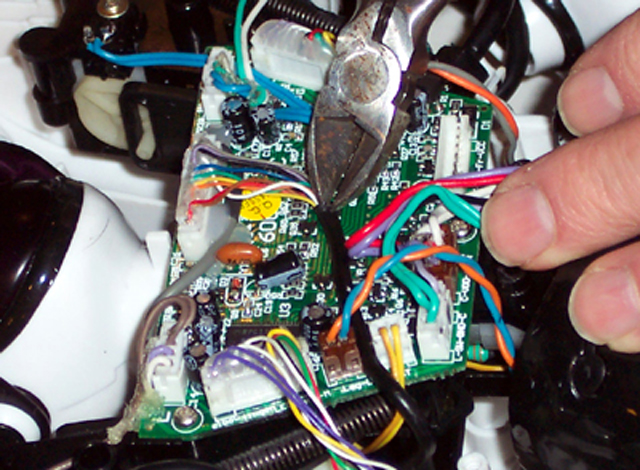
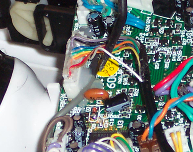
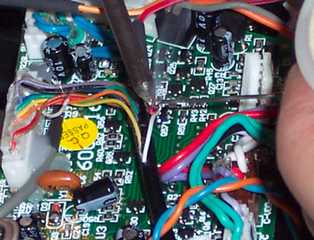
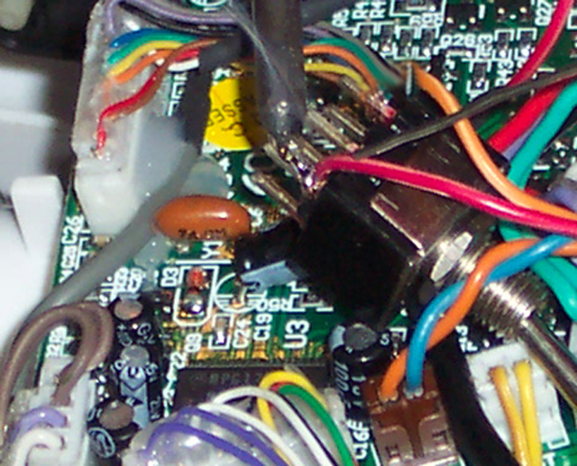
Locate the large black wrapped wire bundle and very carefully cut back some
of the plastic wire coating. Be very carefull to not cut any of the wires.
|
 |
 |
 |
 |
|
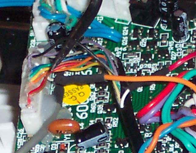
Locate the white wire in the bundle. It should be the third wire from the right end
of the wire connector.
|
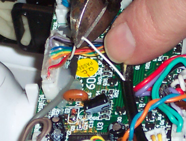
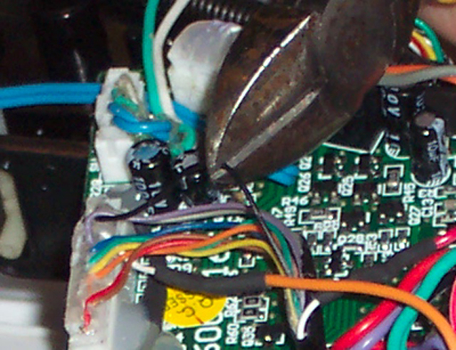
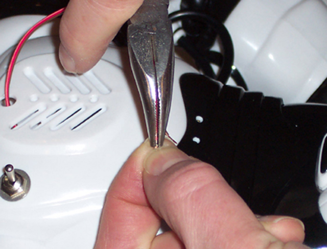
Cut the wire.
|
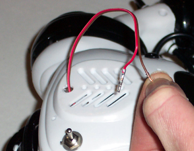
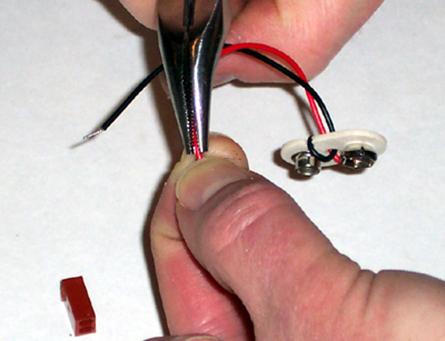
Carefully strip both ends of the wire.
|
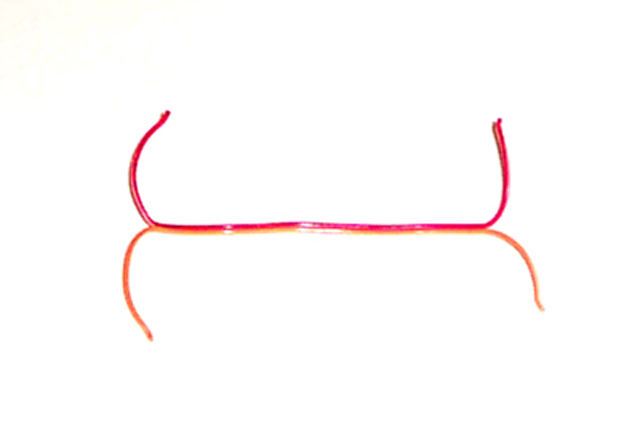
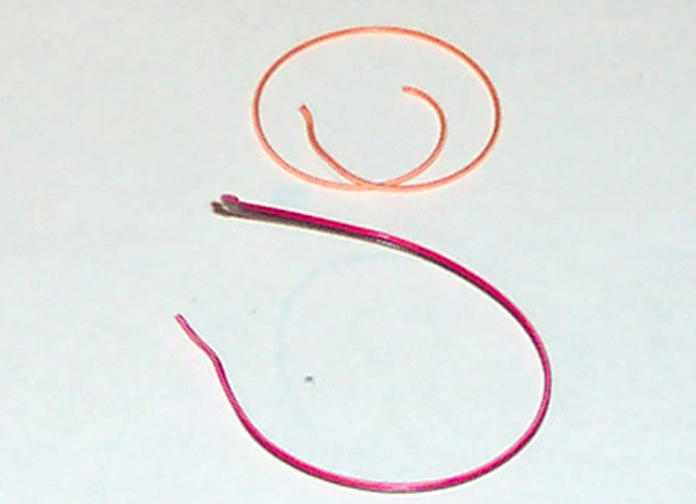
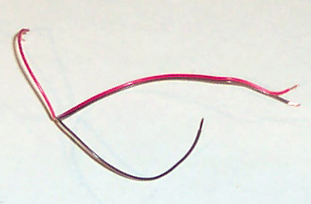
Cut about six inches from the included wire in the kit. Peel off the brown
or black wire and strip both ends of the remaining two.
|
 |
 |
 |
 |
|
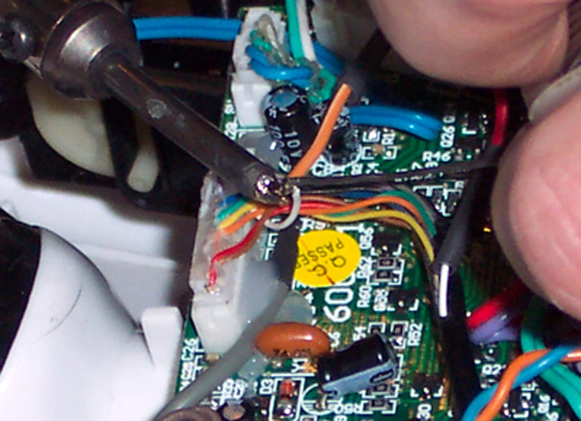
Place about 1/2 inch of shrink tubing over each end of the six inch wire.
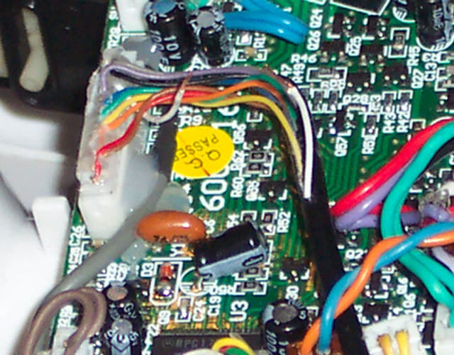
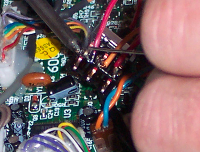
Carefully solder the red wire to the white wire which disappears into the wire bundle.
|
Solder the orange or yellow wire to the white wire that goes to the connector.
|
Slide the heat shrink tubing over the newly soldered connections. Shrink
the tubing with the heat of your hsolder iorn or heat gun.
|
Cut about nine inches of wire from the kit and peel away the orange or yellow wire.
|
 |
 |
 |
 |
|
Strip the ends of the nine inch wire. sperate about three to four inches of one end
of the wire.
|
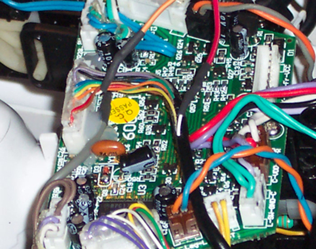
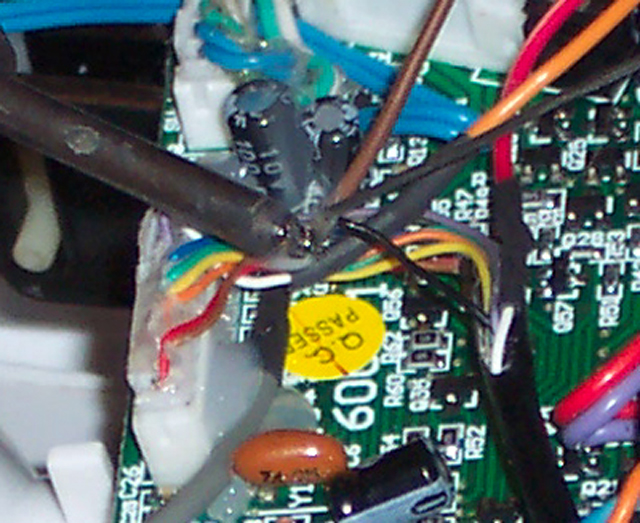
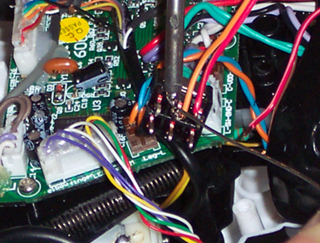
Locate the black wire in the wire bundle.
|
Carefully cut and strip the black wire.
|
Solder the black or brown wire from the nine inch wire to both stripped ends
of the black wire in the Robot.
|
 |
 |
 |
 |
|
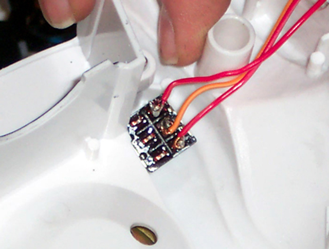
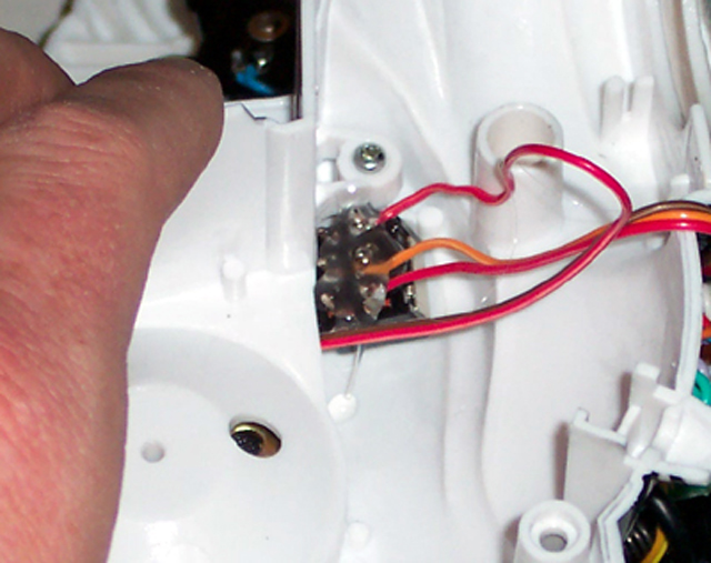
Solder the red wire from the six inch piece to a corner pin on the switch.
|
Solder the orange or yellow wire from the six inch piece to the center pin
of the same row as the red wire on the switch.
|
Solder the red wire from the nine inch piece to the remaining pin in the same row on
the switch.
|
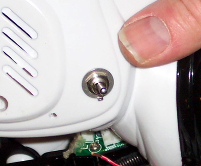
Place the switch in the hole drilled on the back of the robot.
|
 |
 |
 |
 |
|
Screw the nut over the switch to hold it in place.
|
Place a blob of hot glue over the switch wires to help prevent shorts. The
Hot glue is optional, I just like it.
|
Remove the three screws holding the speacker cover in place.
|
Remove the speaker cover.
|
 |
 |
 |
 |
|
Push the remaining end of the nine inch wire through the exsposed wire
access hole.
|
Replace the speacker cover and screw in the three removed screws.
|
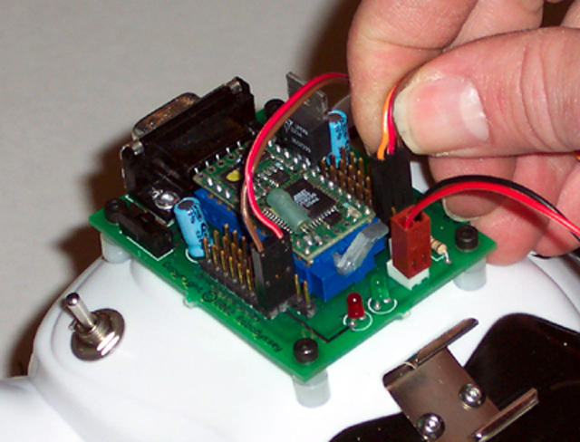
Carefully reconnect the wire cable on the robot back to the circuit board.
|
Loosely place the robot back onto the robot body.
|
 |
 |
 |
 |
|
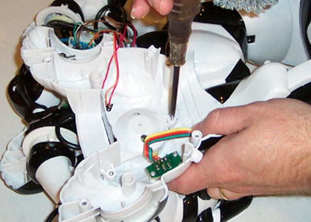
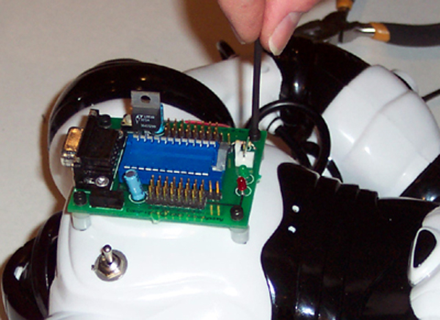
Use the adjustable bracket to mark the location of the holes.
|
Using a #43 bit, drill the holes needed to mount the adjustable bracket.
|
Thread the holes with a 4-40 tap.
|
Attach the adjustable bracket with two 3/8 inch 4-40 pan head screws.
|
 |
 |
 |
 |
|
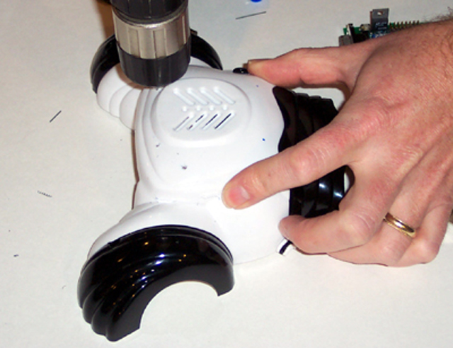
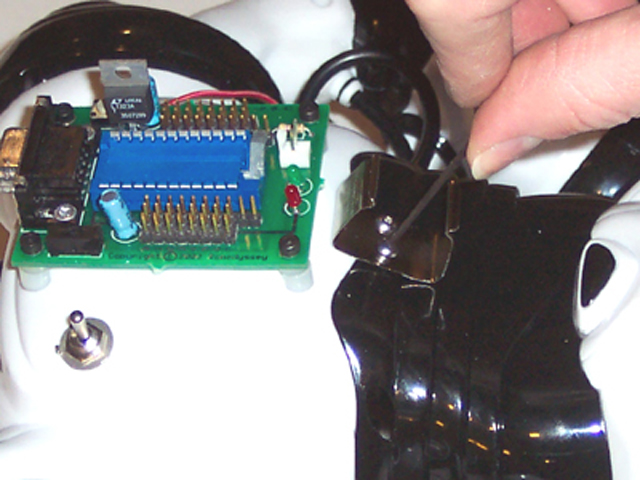
Paying close attention to the guides, push the back plate fully into place.
(note the pointer showing the location of the guides)
|
Carefully re-align the wire stop blocks into thier locations.
|
Place the front plate back on the robot.
|
Screw in the 4 screws holding the front and back of the robot together.
|
 |
 |
 |
 |
|
Crimp the Molex terminals onto the ends of the nine inch wire. For detailed
instructions on making molex cables visit the Cable Assembly Guide |
View with one molex treminal crimped into place.
|
Attach the motherboard with the 5/8 inch 4-40 screws and 3/8 inch spacers.
(3/8 inch spacers could be a 1/8 inch and a 1/4 inch stacked on top of each aother as shown)
|
Attach the battery clip with the 1/4 inch 4-40 pan head screws.
|
 |
 |
 |
 |
|
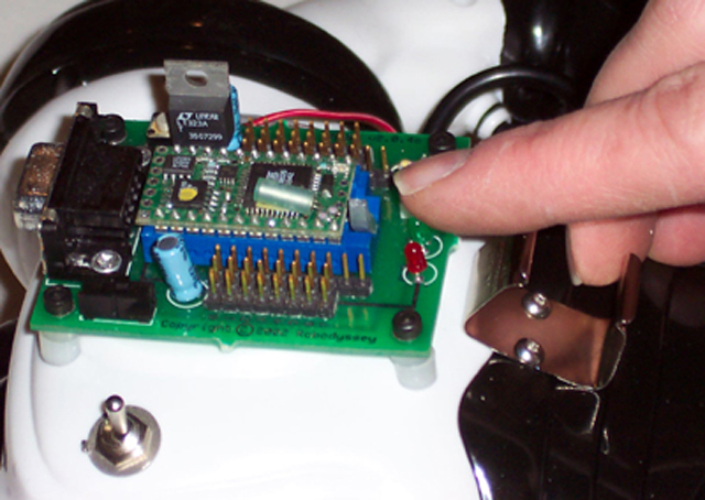
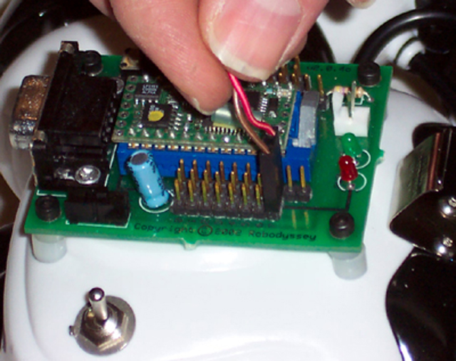
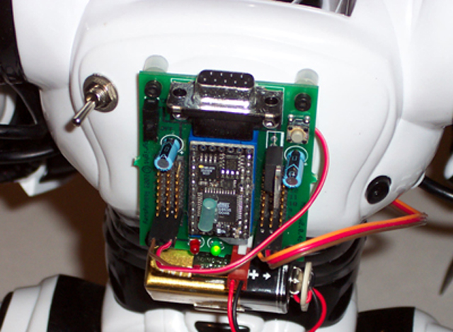
Lift the lever on the socket in the up position. Place the BX-24 into the motherboard socket.
Be sure the cylinder shaped capacitor is near the locking lever as shown. Lock
the chip in place by pushing down the lever.
|
Plug in the molex cable. It is absolutely imperative that the brown wire is closer to
the edge of the board and the lighter wire is closest to the chip. I like to use pin 12
for the robot operation. It will be labled pin 8 on the motherboard. (See picture)
|
Locate these parts for assembly of the nine volt battery clip.
|
Crimp the terminals onto the battery clip wire.
|
 |
 |
 |
 |
|
Carefully insert the red battey wire into the connector. With the connector ridge facing you,
the red wire gets inserted on the right. See next frame.
|
When the connector is properly assembled, the connector should plug in with the red wire
closest to the two led lights on the motherboard.
|
Attach the Sharp Sensor to the adjustable bracket using two of the 3/8 inch
4-40 pan head screws.
|
Adjust the bracket and tighten the screws on the side to lock it into place.
|
 |
 |
 |
|
Attach the sharp sensor cable to the sensor.
|
Plug the sensor cable into the motherboard. It is absolutely imperative that the brown wire is closer to
the edge of the board and the lighter wire is closest to the chip. I like to use pin 13
for the robot operation. It will be labled pin 9 on the motherboard. (See picture)
|
Clip the battery into the holder and plug the battery into its terminal.
You are ready to download!
|
Robosapien is a trademark of WOW WEE